Intertron Model 109A


Single Phase Resistance Welding Controller
All the Features of Your Most Powerful Control with the Ease of Thumb Wheel Operation

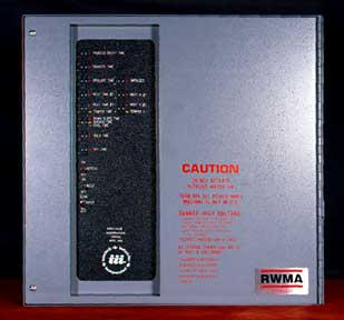
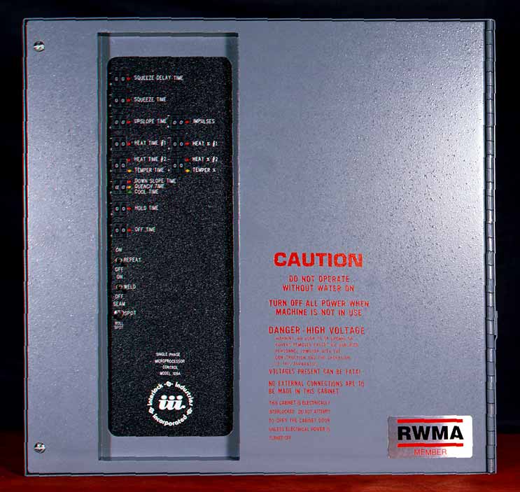
Model 109A — Detail Picture — Cabinet Style “A”
Standard Features:
- Spot Weld Operation
- 4 Modes of Thumb Wheel Switch Operation
- Triple Foot Switch Input with Two Stage Initiation
- Triple Palm Button Input with Dual Mode Anti-Tie Down Initiation
- 87 Degree Fire Limit
- Half Cycle Alternate Polarity
- Direct Interface to Model 375, 10 Station Intertron Scanner
- Weld/No Weld Switch
- Pressure Switch Input
- Emergency Stop Switch Input
- LED Warning Signal if the Foot Switch is Closed upon Power Up
- Thumb Wheel Switches Operational Integrity Test with Visual Feedback
Note: Model 109 is identical to 109A less the “# impulses” thumb wheel.
Optional Features:
- Butt weld Operation
- Seam weld Operation
- Seam – Spot – Roll On/Off Switch
- 50 Hz or 60 Hz Operation
- Magnetic Circuit Breakers
Specifications:
- Control Transformer:
- Standard Input:
- 60 Hz 200VAC-220VAC-240VAC-440VAC-480VAC @ 150VA
- Optional Inputs:
- 60 Hz @ 150VA
- 50 Hz 240VAC-380VAC-415VAc-480VAC-575VAC @ 150VA
- Cabinet Sizes:
- Style “A” Cabinet: 16.5″ x 16.5″ x 9″ (H x W x D)
- Style “B” Cabinet: 17″ x 20″ x 11″ (H x W x D)
- Style “C” Cabinet: 30″ x 20″ x 11″ (H x W x D)
- Style “D” Cabinet: 36″ x 30″ x 12″ (H x W x D)
- Valve Outputs:
- Squeeze 120VAC-20VA max
- Butt Weld Clamp 120VAC-20VA max (Optional)
- Seam/Roll Spot Relay On/Off Output 120VAC-20VA max (Optional)
- Contractor Sizes:
- 300 Amp Free Convection Air-Cooled Contactor in Style “B” Cabinet
- 600 Amp & 1200 Amp Indirect Water Cooled Contactor in Style “A” or “B” Cabinet
- 600 to 3200 Amp Direct Cooled Contactors in Style “B” Cabinet
Intertron Products:
Single Phase:
Three Phase:
Modes, their Capabilities, and How they are Initiated:
MODE “A” INITIATED BY FS1 AND FS2
| squeeze delay time | 00-99 |
| squeeze time | 00-99 |
| upslope time | 00-99 |
| impulses | 00-99 |
| heat time #1 | 00-99 |
| heat % #1 | 00-99 |
| down slope/cool time | 00-99 |
| hold time | 00-99 |
| off time | 00-99 |
MODE “B” INITIATED BY FS1 AND FS3
| squeeze delay time | 00-99 |
| squeeze time | 00-99 |
| upslope time | 00-99 |
| impulses | 00-99 |
| heat time #2 | 00-99 |
| heat % #2 | 00-99 |
| down slope/cool time | 00-99 |
| hold time | 00-99 |
| off time | 00-99 |
MODE “C” INITIATED BY FS1 AND FS4
| queeze delay time | 00-99 |
| squeeze time | 00-99 |
| upslope time | 00-99 |
| impulses | 00-99 |
| heat time #1 | 00-99 |
| heat % #1 | 00-99 |
| quench/cool time | 00-99 |
| temper time | 00-99 |
| temper % | 00-99 |
| hold time | 00-99 |
| off time | 00-99 |
MODE “D” INITIATED BY FS1 AND FS2 OR FS1 AND FS3
| squeeze delay time | 00-99 |
| squeeze time | 00-99 |
| upslope time | 00-99 |
| impulses | 00-99 |
| heat time #1 or #2 | 00-99 |
| heat % #1 or #2 | 00-99 |
| cool time | 00-99 |
| hold time | 00-99 |
| off time | 00-99 |
